Containment and Reference Systems
|
1. Create a folder called Containment somewhere under your personal directory (e.g. C:\Users\jdoe\Documents\Tutorials\Containment). 2. Download the Containment.zip data for this exercise and extract the files to your newly created Containment directory. |
This tutorial demonstrates pitfalls to avoid when exploring containment as it pertains to spatial relationships between features and projections. In theory, if feature A is contained by feature B in one reference system, that feature should always remain contained in feature B in any other reference system. This can be made intuitive by visualizing a point drawn inside of a square on a flexible rubber sheet. If you are to stretch and pull the rubber sheet in any possible direction that point will always remain inside the square.
More formally, if a feature is bounded to the north, south, east and west by another feature, it will always remain bounded by those same locations regardless of reference system used. However, in this tutorial you will learn that this spatial property may not always be preserved with some GIS tools such as ArcGIS’ Select by Location tool.
Step 1: Loading the data and performing a simple selection
Step 2: Checking for containment in a different reference system
Step 3: Densifying the features
Open the Containment.mxd document.
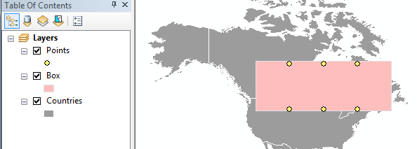
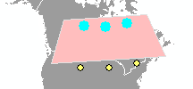
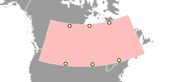
The map consists of six points all of which fall inside of the pink rectangle. A map of North America is shown in the background as a reference. The reference system used in this example is Miller (a cylindrical projection).
To confirm that the points fall inside the rectangle, open the Select by Location tool from the Selection pull-down menu.
Set the section parameters as shown in the following figure.
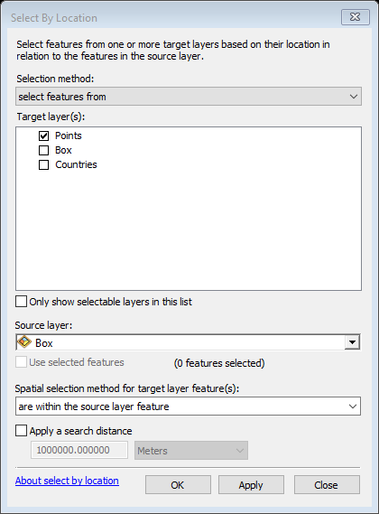
Click OK to perform the selection.
You should now see all six points selected in the map.
Clear the selected features by clicking on the Clear
icon ![]() .
.
Next, we will perform the same selection in a different reference system.
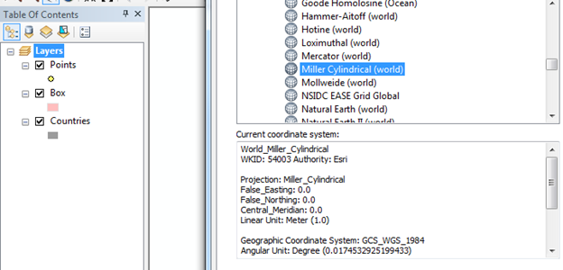
The Select by Location tool inherits the data frame’s reference system and not the input layer’s reference system so we’ll change the data frame to a conical projection.
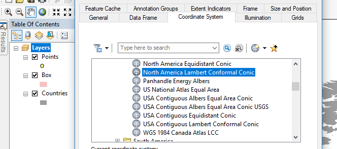
Right-click the data frame (named Layers) and select Properties.
Under the Coordinate System tab, change the reference system to Projected Coordinate System >> Continental >> North America >> North America Lambert Conformal Conic.
Click OK to close the properties window.
If you’re presented with a warning window, click “Yes” to continue. The warning is indicating that the underlying datums between the reference systems differ.
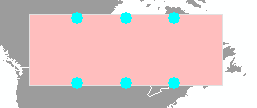
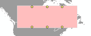
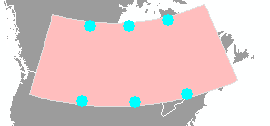
Note how three of the points are now outside of the rectangle (which now looks more like a trapezoid in this projection).
Re-run the Select by Location tool to confirm that the tool is working off of the data frame’s projection.
Sure enough, just three points are selected.
When ArcMap re-projects polylines or polygons, it does so only for the vertices (vertices are the points that define the ends of the line segments). The line segments are drawn after the vertices are re-projected but the segments themselves are not re-projected to reflect their true shape in this difference reference system.
Clear the selected features by clicking on the Clear
icon ![]() .
.
When exploring containment between features, it’s usually best to stick to the reference system that was used to map the features since it would be safe to assume that the original author would have intentionally mapped this spatial relationship between the features. However, if analyzing containment in a different reference system is desired or needed, one solution is to densify the edges of the features before changing reference systems
ArcMap offers two densifying tools: Densify (under the Editing Toolbox) and Geodesic Densify. You would use the former if all line segments defining the features were intentionally digitized in the layer’s native reference system you are starting off of (i.e. a straight line segment was indeed intended to be straight in the native reference system). You would use the latter if the line segments were automatically generated from vertex locations and the segments connecting the vertices are believed to be the shortest distance between the vertices along the earth’s surface (i.e. geodesic lines).
In this example, we will assume that the line segments are intentionally digitized as being straight in their native reference system. We’ll therefore demonstrate the Densify tool.
Set the data frame’s coordinate system back to the Miller projection via Project Coordinate System >> World >> Miller Cylindrical (world).
Click OK to close the property window.
Your map should be back to its original reference state.
The pink rectangle is defined by just four vertices (one at each corner). If we want the line segment to follow the transformation that projection one would expect in a different reference system, we need to add more vertices along the line segments since the vertices are the actual geometric elements being re-projected.
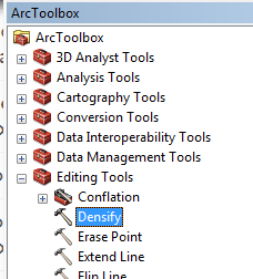
From the ArcToolbox, select the Editing Tools >> Densify.
Note that the densify tool will modify the existing feature and not create a new one as is the case with most other geoprocessing tools.
Fill out the fields as shown in the following figure:
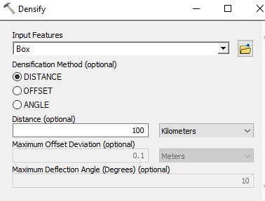
Click OK to run the geoprocess.
The choice of density value will be determined by the level of precision needed as well as the tolerance level set for the data layers.
In our example, the contained features are points, so they do not need to be densified. However, if the contained features were discrete polygons or polylines, then you would probably want to densify those as well.
Next, change the data frame coordinate system back to the North America Lambert Conformal Conic projection as outlined in step 2.
Note how the pink polygon’s edges now reflect their true shape in this new reference system. You can perform the select by location from Step 1 once again to confirm that all size points are indeed selected, as expected.
This ends this exercise.
© Manny Gimond, 7/11/2018