Defining and fixing topological errors
|
1. Create a folder called Topology. On DIA 322 computers, you might want to create this folder in your user Documents folder (e.g. C:\Users\jdoe\Documents\ Topology). On the DIA 222 computers, you might want to create this folder on the D: drive under D:\course number\user name\ (e.g. D:\ES212\jdoe\Topology). 2. Download the data for this exercise by clicking here and uncompress the contents of Topology.zip into your newly created Topology directory. |
In this exercise, you will learn how to define and identify topological errors. Examples of topological rules covered in this tutorial include “must not overlap” and “must not have gaps” rules.
Step 1: Open an existing ArcMap document
Step 2: Creating and defining a new geodatabase topology
Step 3: Checking the topology results
Step 4: Removing gaps in a polygon feature class
Step 5: Fixing polygon overlap errors
Step 6: Fixing boat launch topological errors
Step 7: Identifying and editing polylines that fall outside of a boundary
Step 8: Fixing non-overlapping polygons errors between two different feature class sources
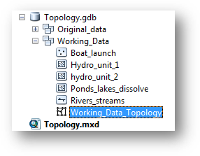
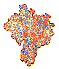
Navigate to the Topology folder and open Topology.mxd with ArcMap.
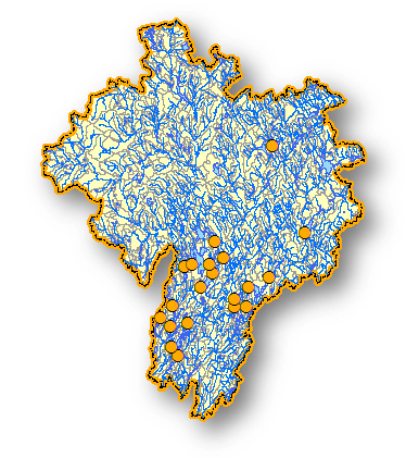
The map project depicts two levels of hydrologic drainage basins: the top-level is defined by the orange and dashed outline, and the sub-basins are symbolized with light yellow polygons. River polylines, lakes/ponds and boat launch sites top off the map.
The purpose of this exercise is to identify topological errors that may have resulted from digitizing or post-processing errors. We want to preserve the following topological relationships:
·
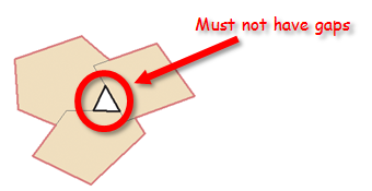
There must be no gaps between the sub-basin (Hydro unit
level 2) polygons.
·
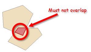
There must be no overlap between the sub-basin (Hydro unit
level 2) polygons.
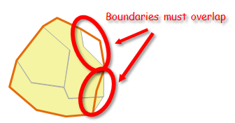
· The top level basin (Hydro unit level 1) boundary must coincide with the sub-basins (Hydro unit level 2) border boundaries.
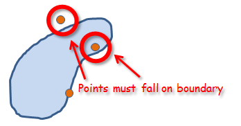
·
The boat launch point features must fall on the ponds and
lakes polygon boundaries.
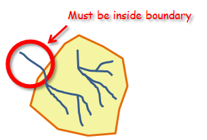
·
Rivers and streams must not extend beyond the top-level
basin (Hydro unit level 1).
In some cases, the aforementioned requirements can be met with a careful visual analysis of the map. However, in most cases, many of the aforementioned rules can be easily overlooked. A systematic/automated approach to identifying topological anomalies is often preferred. You will use ArcGIS’ Topology tool to define and identify topological errors.
On the right-hand side of the ArcMap interface, expand the Catalog tab.
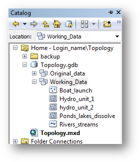
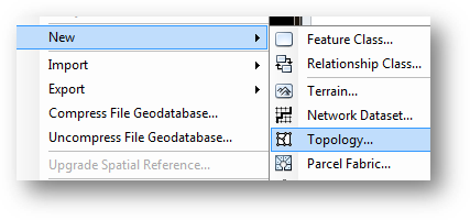
Right-click on the Working_Data feature dataset under the Topology geodatabase and select New >> Topology.
In the New Topolgy window, click Next.
Keep the default topology name and change the cluster distance to 5 meters.
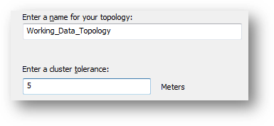
The cluster tolerance defines the minimum spacing between vertices within a feature class and across feature classes taking part in a topology. The tolerance distance should be chosen carefully.
Click Next.
Select all layers. They will all take part in this topology.
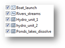
Click Next.
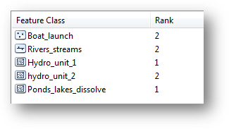
When a topology is validated, vertex position can be modified during the cracking/snapping process. When more than one layer takes part in a topological rule, you need to define which layer will have its vertices position adjusted.
In this exercise, we will assume that the top level drainage basin and the pond/lake boundaries are positionally more accurate—meaning that all other features taking part in a topology will have their vertices position adjusted if deemed necessary.
Set the ranks as shown below:
Click Next.
In this step you will define all rules that will take part in this topology.
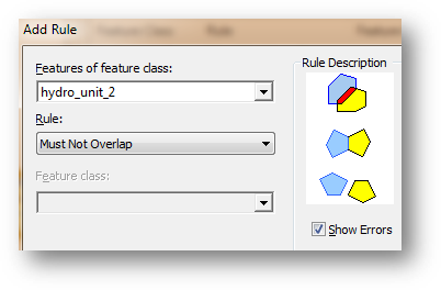
Click the Add Rule button ![]() .
.
Set hydro_unit_2 as the feature class.
Select the Must Not Have Gaps rule.
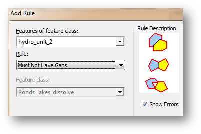
Click OK.
Next, you will add the second rule.
Click the Add Rule button again.
Set hydro_unit_2 as the feature class.
Select the Must Not Overlap rule.
Click OK.
Following the same steps, you will add three more rules (note that the next set of rules involve two features classes instead of one).
|
Boat_launch |
Must be covered by boundary of |
Ponds_lakes_dissolve |
|
Rivers_streams |
Must be inside |
Hydro_unit_1 |
|
Hydro_unit_1 |
Area boundary must be covered by boundary of |
Hydro_unit_2 |
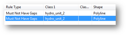
The list of rules should look like this:
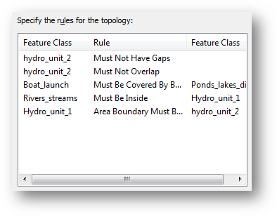
When you are done adding the other three rules, click Next.
The next window displays a summary for the new topology.
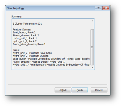
Click Finish.
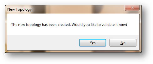
When asked if you want to validate the topology now, click Yes.
The new topology can be added to your map document as a layer. The topology layer symbolizes the features that break the topological rules.
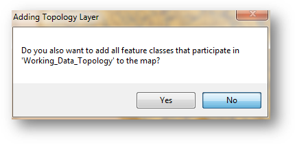
Drag and drop Working_Data_Topology into your map document.
Click No when asked if you want to add all feature classes that participate in the topology (the feature classes are already in the map document).
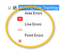
Note that the topology layer has three symbols, one for each geometric primitive (polygon, polyline and point/vertex).
You can scan for topological errors on the map, or you can list the errors in a table. To bring up the table, you must first start an edit session.
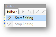
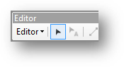
Open the Editor toolbar by clicking the Editor Toolbar button.
In the Editor toolbar, select Start Editing from the Editor pull-down menu.
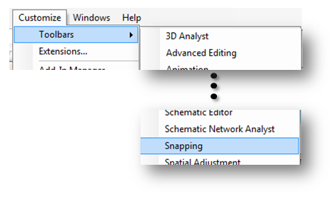
From the Customize pull-down menu, select Toolbars >> Topology.
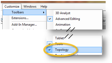
You should now see a floating Topology toolbar.
![]()
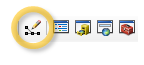
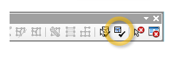
In the Topology toolbar, click on the Error Inspector button.
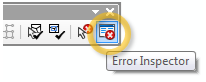
This opens the Error Inspector table. This table lists all topological errors in your map document. You can list the errors by topological rules defined in your topology.
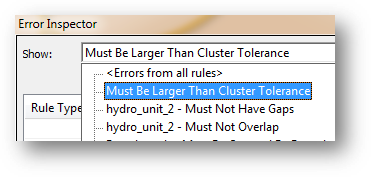
One rule that you did not explicitly define but takes part in topology nonetheless is the “Must be larger than cluster tolerance” rule (remember that you specified a cluster tolerance of 5 meters when you defined the topology). These errors flag all features who’s vertices were within each other’s cluster tolerance.
In the Error Inspector window, select “Must be larger than cluster tolerance” from the Show pull-down menu.
Next, unselect Visible Extent only and click Search Now.
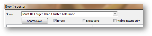
You should have 33 errors. Most of these errors are associated with the River & Streams polyline layer.
Right-click on the first error and select Zoom to.
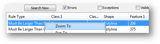
You might see something like the following graphic:
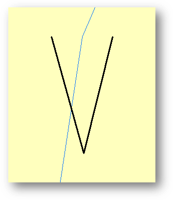
The light blue line represents the Rivers & Streams layer after the topology validation. The black line shows the segment of original River & Streams layer that did not satisfy a topology rule (cluster tolerance). The visual representation may not make much sense unless you bring up the original layer. A copy of the Rivers & Streams layer was saved in the geodatabase. You will add this layer for comparison in the following step.
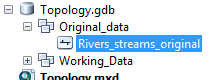
Using the Add Data tool ![]() , you will
add Rivers_streams_original layer which is located under the
Original_data feature dataset in the Topology geodabase.
, you will
add Rivers_streams_original layer which is located under the
Original_data feature dataset in the Topology geodabase.
Having the original layer displayed in the map document helps
understand what happened. Because the original vertices were within the cluster
tolerance, the software “collapsed” the vertices into a single vertex. In the
process, the polyline feature changed in length and orientation! It is
important to remember that once a topology is validated, all vertices/points
falling within the cluster tolerance are altered. This process is not
reversible! It is therefore good practice to make a copy of the feature whose
topology will be validated before the validation is performed.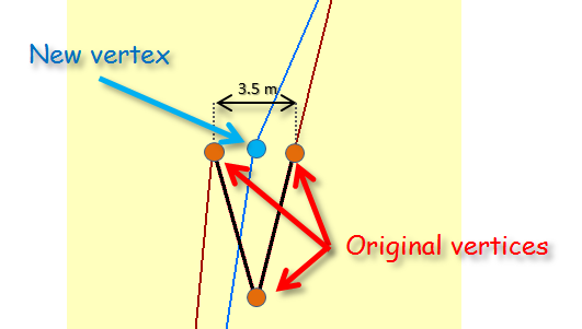
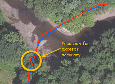
If you want to minimize the chance of having vertices snapped to new locations, you can set the cluster tolerance to the lowest value (usually 0.001 map units). However, there are advantages to defining larger cluster tolerances. In our example, the original polyline precision far exceeds its intended accuracy. This introduces redundant vertices and sometimes misleading representation of real world features.
In the TOC, uncheck the Rivers_streams_original layer.
Let’s move on to another topology rule: The Hydro unit level 2 layer must not have gaps.
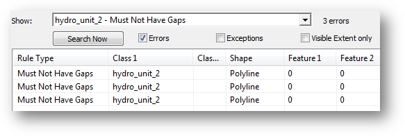
In the Error Inspector window, select hydro_unit_2 – Must Not Have Gaps.
Make sure that Visible Extent only is unchecked and click Search Now.
You should see three errors.
Right-click the third error in the list and select Zoom To.
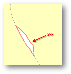
Gaps between polygons can be difficult to spot visually. This can be important if the intent is to represent/model a continuous field.
Unlike the “Must be larger than cluster tolerance” errors, the “must not have gap” errors require user feedback. We therefore need to remove all gaps identified in the topology. You will learn how to fix topology errors in the next step.
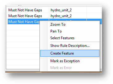
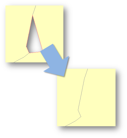
The Error Inspector window will sometimes offer “fixes” for the problem. These proposed fixes can be accessed by right-clicking on the error record. You will use the proposed fix to remove this gap.
Right-click on the third (last) record in the table. You will note that one solution is offered to resolve the error: Create Feature.
Select Create Feature.
A new polygon now replaces the gap. However, this raises a new issue. Was the original intent to have a standalone watershed unit in the space occupied by the gap, or was that space meant to be occupied by one of the two adjoining polygons? In our example, we will assume that the gap was to be occupied by the polygon to the right. We will therefore merge the newly created polygon with the existing one.
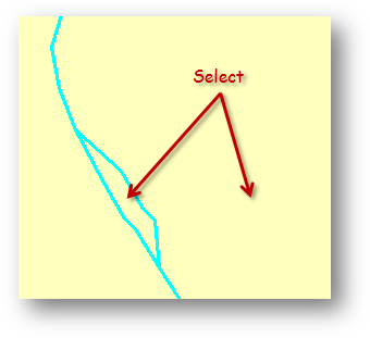
Using the selection tool ![]() , press and hold
the shift key and select both the newly created polygon and the
larger polygon to its right.
, press and hold
the shift key and select both the newly created polygon and the
larger polygon to its right.
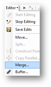
In the Editor toolbar, select Editor >> Merge.
Select hydro_unit_2 – ME as the feature to merge with.
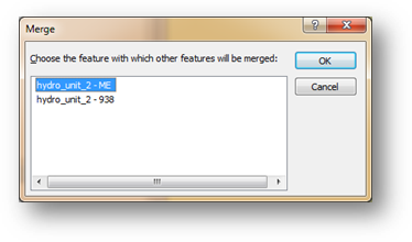
Click OK.
You may have noticed that the gap you just fixed is no longer listed in the Error Inspector window (if it’s still present, click the Search Now button to refresh).
Let’s move on to the next error.
Right-click the second (or last) error in the list and select Zoom to.
Follow the same steps used to fix the last gap. You will merge the newly created polygon with the polygon to its right (hydro_unit_2-ME).
You are now left with just one “must not have gaps” error.
In the Error Inspector window, right-click on the remaining error and select Zoom-to.
The entire feature is highlighted. This is normal. Since the outer edges of the Hydro unit level 2 layer do not share boundaries with neighboring features, the software flags this as an error. This is an error that can be ignored, we will therefore flag it as such.
In the Error Inspector window, right-click on the remaining error and select Mark as Exception.
This will remove the error from the list.
Next, you will fixed polygon overlap errors.
In the Error Inspector window, select hydro_unit_2-Must Not Overlap then click the Search Now button.
You should see three errors listed.
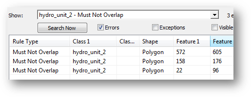
Right-click on the first error and select Zoom to.
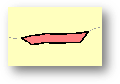
Remember that the rose colored polygon is a representation of the topological error.
Int the TOC, turn off the Working_Data_Topology layer.
 .
.
At first glance, nothing seems wrong with the feature—there is no indication of overlap. Any overlap will be masked by filled polygon. To ‘unmask’ the overlap, we will need to temporarily set the fill color to ‘no color’.
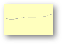
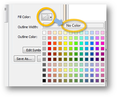
In the TOC, double-click the Hydro unit level 2 symbol and set the Fill Color to No Color then close the Symbol Selector window.
This last step only displays the features’ outlines thus revealing the area of concern.
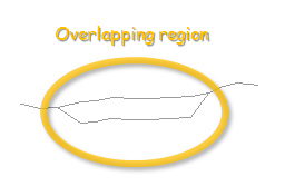
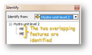
To convince yourself that two the area-of-interest is the result of overlapping polygons, use the identify tool.
Click on the Identify tool ![]() .
.
Select the overlapping region.
In the Identify window, make sure that Hydro unit level 2 layer is selected.
Note that two features are identified.
Right-click on the first record in the Error Inspector window.
To fix the problem, the error inspector window provides three solutions: subtract, merge and create feature.
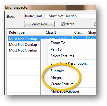
We will choose to merge the overlapping area with the polygon to the south.
Select Merge.
Choose polygon ID 605.
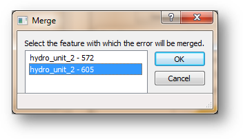
Click OK.
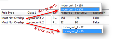
You will follow the same procedure to resolve polygon overlap conflicts for the other two errors. The following graphic presents the merge options to choose.
Next, we will tackle the boat launch must be on the edge of ponds and lakes topological errors.
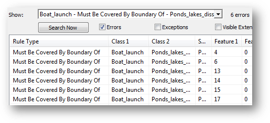
In the Error Inspector window, select Boat_launch – Must Be Covered By Boundary Of – Ponds_lakes_dissolve.
Click Search Now (make sure that Visible Extend only option is unchecked).
Seven errors should be listed.
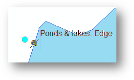
In the Error Inspector window, right-click the first record and select Zoom to.
If needed, use the zoom tool to zoom in further on the point of interest.
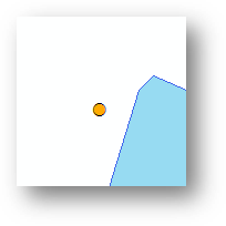
The point is clearly not on the Ponds & Lakes boundary. If you right-click on the error record, you’ll note that the Error Inspector tool does not offer an automated solution to the problem. This entails a manual edit of the point.
First, you will need to ensure that the snap tool is properly set up to snap points to edges of polygons.
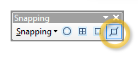
From the Customize pull-down menu, activate the snapping toolbar.
In the snapping toolbar, make sure that the Edge Snapping option is set.
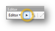
From the Editor toolbar, click on the Edit tool.
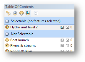
Before we select the point, it might be a good idea to make the point layer the only selectable layer since many layers in our map document overlap one another.
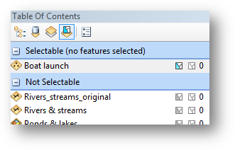
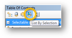
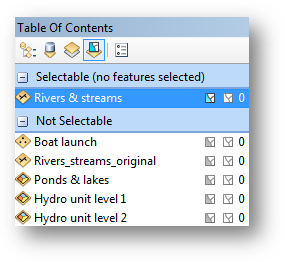
In the Table of Content window, select List By Selection.
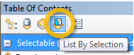
Holding down the Alt key, click on the toggle selectable icon next to the Boat launch layer.
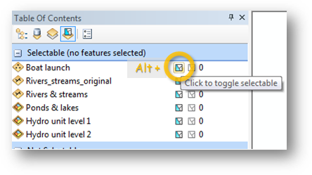
This will ensure that only the boat launch layer is selectable.
In the Editor toolbar, click on the Edit tool.
Select the boat launch point feature and move it to the lake and pond boundary until it snaps to the Ponds & lakes edge then release the mouse button.
To verify that the point coincides with the Ponds & lakes boundary, run the Validate topology in current extent tool from the Topology toolbar.
After running the tool, you may need to refresh the Error Inspector window by clicking Search Now.
You should now have only 6 remaining records.
Repeat this procedure for the remaining six errors.
Next, we will search for river and stream polylines that do not meet the “Rivers_streams must be inside Hydro_uni_1” topology rule.
In the Inspector window select Rivers_streams - must be inside - Hydro_uni_1 then click Search Now.
You should see a single record.
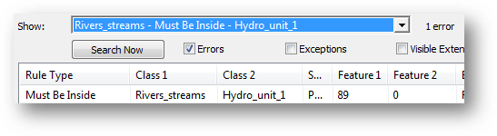
In the Error Inspector window, right-click on the record and select Zoom to.
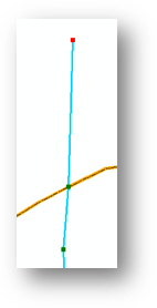
You should spot the culprit polyline along the hydraulic unit northern boundary.
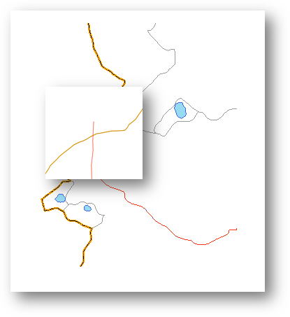
When a topology is validated, ArcMap will not only merge vertices that are within a defined tolerance, but it will also create new vertices where features taking part in a topology intersect. This means that the line segment extending beyond the hydrologic unit boundaries is terminated on one end by that boundary. The solution is simply to select and delete that line segment. But first, you will need to make the rivers and streams layer selectable.
In the Table of Content window, select List By Selection.
Holding down the Alt key, click on the toggle selectable icon next to the Rivers & streams.
In the Editor toolbar, click on the Edit tool.
In the TOC, if the Rivers_streams_orginal layer is till marked as visible, make it invisible.
Using the edit tool pointer, double-click on the polyline. This will expose its nodes.
In the Edit Vertices toolbar (this toolbar should have appeared after displaying the nodes), select Delete vertex.
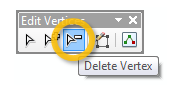
Using the delete vertex cursor, select the top node.
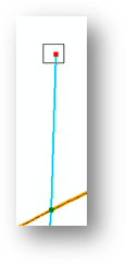
Press the F2 key to accept the changes. The problematic line segment should be gone.
In the Error Inspector window, select the last topology rule (Hydro_uni1_1 – Area Boundary Must Be Covered By Boundary of -- hydro_unit_2). Then click on Search Now.
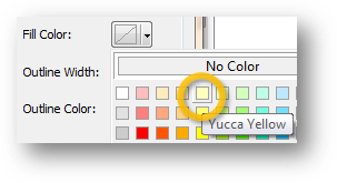
At this point you might want to revert the Hydro unit level 2 layer back to its original symbology (i.e. convert the fill color back to Yucca Yellow.
In the Error Inspector window, right-click on the top record then select Zoom to.
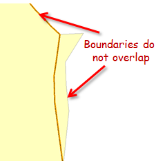
The Error Inspection window does not offer an automated solution therefore it will have to be fixed manually.
In the Table of Content window, select List By Selection.
If needed, clear all selections ![]() from your
map.
from your
map.
Holding down the Alt key, click on the toggle selectable icon next to the Hydro unit level 2.
In the Editor toolbar, click on the Edit tool.
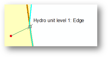
Select the Hydro unit level 2 boundary.
To properly overlap the two boundaries, both layers must share the same nodes. Unfortunately, in an edit session, you can only display nodes one layer at a time. One workaround to this is to use the trace tool.
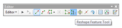
In the Editor toolbar, select Reshape Feature Tool.
With the cursor, create the first sketch point near the area depicted in the following graphic.
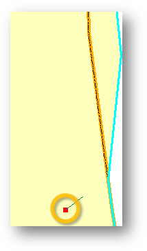
Next, create the second point on the line segment shared by both features.
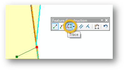
On the floating Feature Construction toolbar, select Trace (this puts you into trace mode).
Next, with the cursor tool active, select the line just north of vertex where the boundaries diverge.
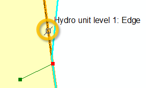
Now you have activated a trace, without pressing the mouse button have the cursor follow the orange line segment as closely as possible until you are on a line segment just above the vertex where the boundaries converge again then left click on any part of that last segment.
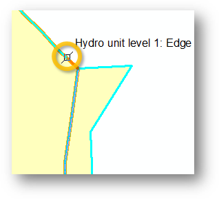
If you are satisfied with your edit, have ArcMap accept the changes by pressing the F2 key. I you are not happy with the edit and want to start over right-click and select delete sketch.
To confirm that the edit resolved the topology error, re-validate this region and click Search Now to refresh the Error Inspector tool.
Apply the same technique to resolve the conflict with the other record listed in the Error Inspector window.
Save your edits and stop your edit session.
Congratulations, you checked and corrected all topological errors.
Save and exit your map document.
![]() Manuel Gimond, last modified on 10/17/2011
Manuel Gimond, last modified on 10/17/2011