Editing Basics
|
1. Create a folder called Editing_basics. On DIA 322 computers, you might want to create this folder in your user Documents folder (e.g. C:\Users\jdoe\Documents\Editing_basics). On the DIA 222 computers, you might want to create this folder on the D: drive under D:\course number\user name\ (e.g. D:\ES212\jdoe\Editing_basics). 2. Download the data for this exercise then extract the contents of Editing_basics.zip into your newly created Editing_basics directory. |
In this exercise, you will be introduced to a few of ArcGIS’ editing tools. You will learn how to create and edit polygon and polyline data. You will also learn how to avoid certain editing pitfalls such as the inadvertent creation of “donut holes”.
Step 2: Create a new polygon feature
Step 3: Digitize a new polygon feature
Step 4: Creating a new feature template
Step 5: Adding a field to an existing layer
Step 6: Splitting an existing polygon
Step 7: Editing the attributes table
Step 8: Adding an ‘Island’ polygon
Step 9: Creating adjoining polygons
Step 10: Setting up the snapping environment
Step 11: Adding vertices to a polyline
Step 12: Extending line segments
Step 13: Adding polyline segments
Navigate to your Editing_basics folder and double-click the Editing_basics.mxd file.
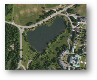
This will launch your new ArcMap session. You should see an aerial image of the Colby Campus.
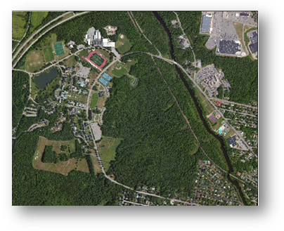
Your first task will be to digitize Johnson Pond.
Before you begin your first digitization task, you will need to create a new polygon feature in the Data.gdb file geodatabase.
To the right of the data view window, click on the Catalog tab.
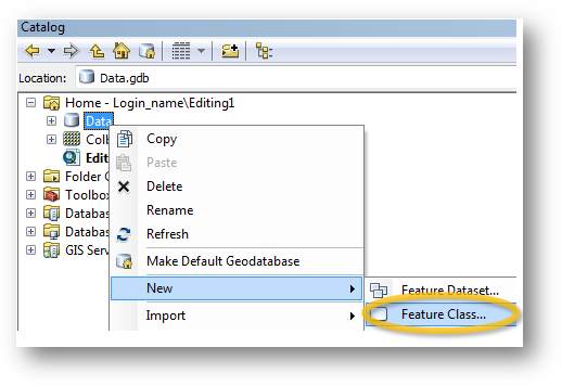
In the Catalog window, right-click on the Data.gdb geodatabase and select New >> Feature Class.
In the New Feature Class window, name the new feature JohnsonPond (make sure not to add spaces) and make sure that Polygon Features is selected as the feature type.
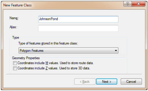
Click Next.
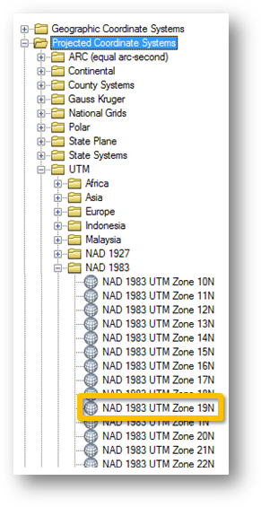
Select Projected Coordinate System >> UTM >> NAD 1983 >> NAD 1983 UTM Zone 19N as the new feature’s coordinate system (this is a popular coordinate system for the State of Maine).
Click Next.
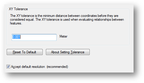
Keep the default XY Tolerance settings.
Click Next.
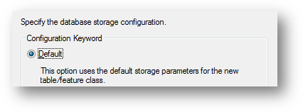
Keep the default database storage configuration.
Click Next.
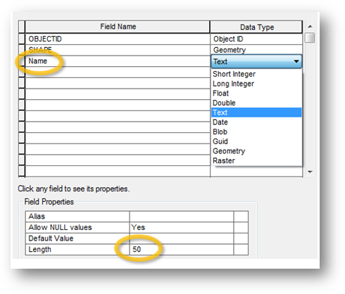
In the Field Name column, add a new field called Name. In the Data Type column, assign the new field set the data type to Text data type. Make sure that the text length is set to 50.
Click Finish.
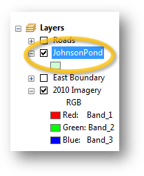
You just created a new (empty) polygon feature class in the Data.gdb geodatabse. ArcMap automatically adds the new feature class to your list of layers in the TOC.
Note that you can also create a new shapefile following the same procedure except that you would right-clicking a folder instead of a geodatabase.
The JohnsonPond layer is currently empty. In the next step you will create a new polygon feature for that layer.
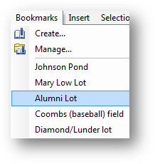
In the Bookmarks pull-down menu, select Johnson Pond.
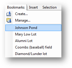
Your map extent should now be restricted to the Johnson Pond water body.
In the next step, you will set the JohnsonPond layer’s transparency to 50%. This will be helpful when digitizing non-linear features since having a non-opaque feature will facilitate seeing the underlying pond as you digitize.
Right-click on the JohnsonPond layer and select Properties.
In the Layer Properties window, select the Display tab and set the transparency to 50%.
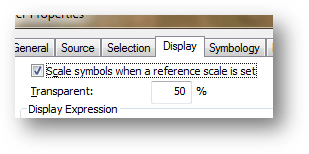
Click OK to close the Layer Properties window.
Next, you’ll start the edit session.
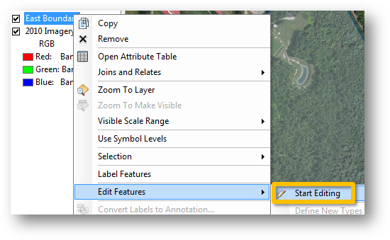
Right-click on the JohnsonPond layer and select Edit Features >> Start Editing.
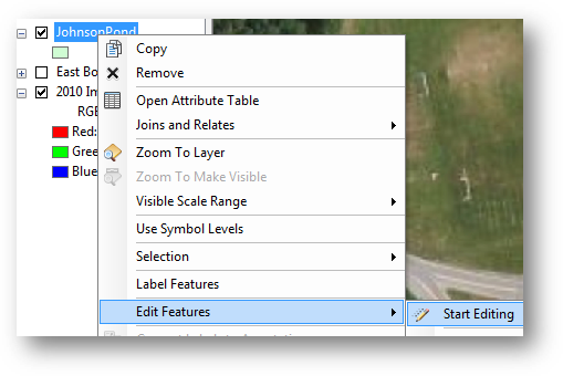
When you start an edit session, a Create Features window pane pops up on the right-hand side. The Create Features window lists all editable layers, and displays the corresponding map symbol next to each layer. These are known as feature templates.
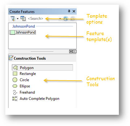
Select JohnsonPond in the Create Features window.
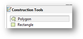
A list of construction tools will appear at the bottom of the window.
Select Polygon.
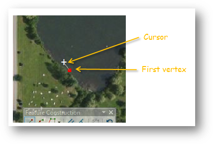
You digitize polygons by creating vertices. The vertices define the points for each line (or edge) defining a polygon.
Move your mouse pointer anywhere along Johnson Pond’s shoreline and left-click. This creates the first vertex.
Continue adding vertices along the edge of the pond. The vertices define the polygon boundary.
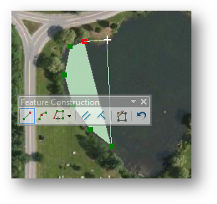
|
Here are some digitizing tips you might find helpful: · To pan around the map during an edit session, click and hold the middle mouse button (wheel) · To zoom in our out of the map during an edit session, scroll the mouse wheel ·
If the Feature Construction toolbar · If you make a mistake while digitizing, press ctrl+Z keys to undo the last edit · To delete an ongoing edit, right-click and select Delete Sketch. |
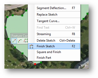
After adding the last vertex, right-click and select Finish Sketch (alternatively, you can press the F2 key). This step finalizes the creation of the new polygon.
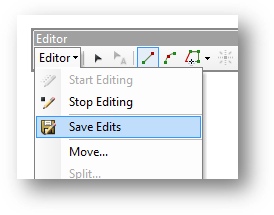
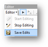
Digitized features do not get saved to the data file (shapefile or geodatabase) until you explicitly instruct ArcMap to do so.
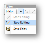
In the Editor toolbar, click on Editor >> Save Edits.
Next you will edit an existing polygon (aka feature class).
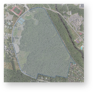
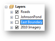
Right-click the East Boundary layer and select Zoom to Layer.
Make the East Boundary visible in your data view
(i.e. check the East Boundary box ![]() in the TOC)
in the TOC)
Note that once you made the East Boundary layer visible in the map document, its feature is added to the Create Features template. This is because the East Boundary feature class resides in the same workspace as JohnsonPond (i.e. …\Editing1\Data.gdb).
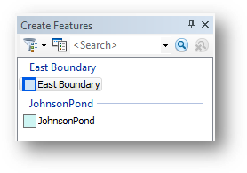
All feature class or shapefile in a common workplace can be accessed within a same edit session. This can pose a problem if the wrong feature is selected in the Feature Templates. It is therefore best to remove (or turn off) all layers not used in an edit session. In this case, we will turn off JohnsonPond so that we don’t accidently edit it.
In the TOC, turn off (uncheck) JohnsonPond.
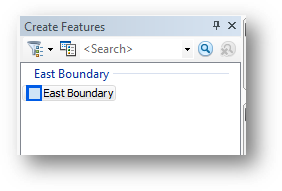
Your Create Features window should now only display East Boundary.
Next, we will add a new field to the East Boundary feature class.
Open East Boundary’s attribute table by right-clicking on the layer in the TOC and selecting Open Attribute table.
New fields can be added in the Table window, however if you are in an edit session, you will notice that the Add Field is ghosted out.
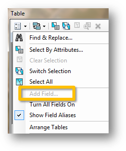
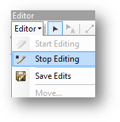
We therefore need to temporarily stop the edit session in order to add a new field.
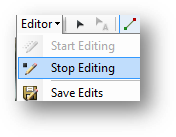
From the Editor toolbar, select Editor >> Stop Editing.
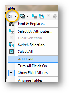
In the attribute table window, select Add Field
from the Table Options pulldown list ![]() .
.
In the Add Field window, name the new field “Type” and make it a “Text” field and set the length to 50 characters.
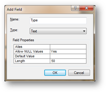
Click OK to close the Add Field window.
Close the attributes table.
Restart the edit session by right-clicking the East Boundary layer and selecting Edit Features >> Start Editing.
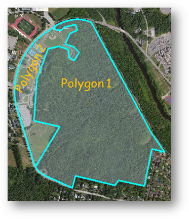
In this step, you will delineate the wooded section of the eastern boundary. Since an existing polygon covers the area-of-interest, we do not want to create a new overlapping polygon. Instead, we will split the existing polygon.
In the Editor toolbar, click on the Selection
tool ![]() .
.
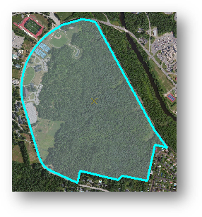
In the Data View window, select the East Boundary polygon.
The polygon edge should be highlighted in cyan.
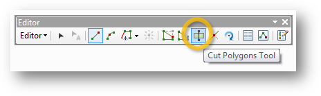
In the Editor toolbar, select Cut Polygons tool.
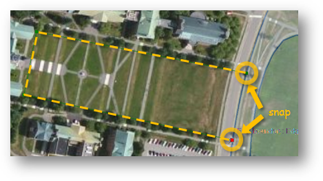
Zoom in to the southern section of the wood/field boundary.
Hover the cursor over the edge of the East Boundary layer until you see the cursor “snap” to the boundary line (a square box will indicate when the cursor is snapped to the boundary edge).
This ensures that the first digitized vertex is interpreted as belonging to the existing boundary edge. If the first vertex does not snap to the existing edge, the split polygon may fail.
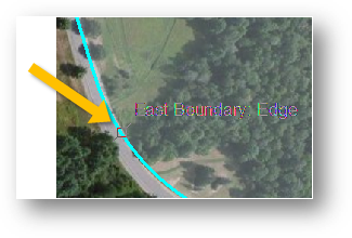
With the cursor snapped to the edge, click the left mouse button to add your first vertex.
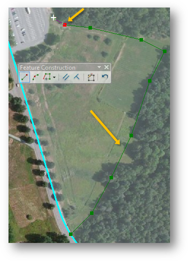
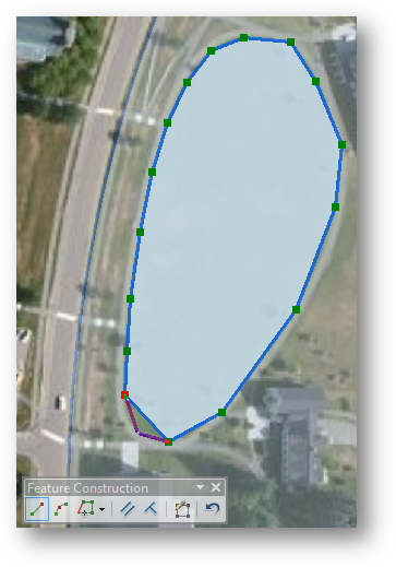
Delineate the wood/open area by adding vertices.
|
Here’s a reminder of digitizing tips you might find helpful: · To pan around the map during an edit session, click and hold the middle mouse button (wheel) · To zoom in our out of the map during an edit session, scroll the mouse wheel ·
If the Feature Construction toolbar · If you make a mistake while digitizing, press ctrl+Z keys to undo the last edit · To delete an ongoing edit, right-click and select Delete Sketch. |
When you reach the northern edge of the boundary, hover your mouse cursor over the edge until you see the cursor snap, then click on the left mouse button to place your last vertex.
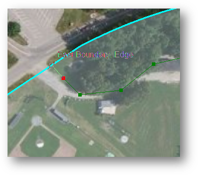
To finish the sketch, right-click anywhere on the map and select Finish Sketch (or press the F2 key).
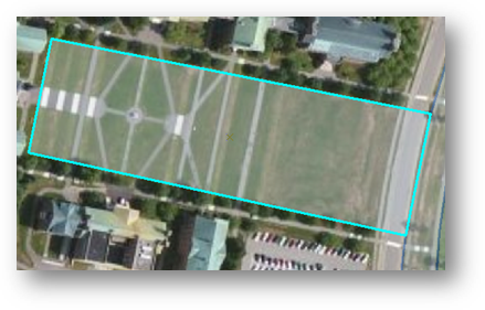
The East Boundary polygon is now split into two non-overlapping polygons.
Next, you will assign attribute values to both polygons.
Make sure that both polygons are still selected (they should both be outlined with a bright cyan color).
If your attribute table is not open go to the Editor toolbar and open the Attributes table.
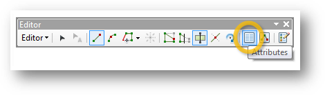
The Attributes table will open in the right hand side of the ArcMap window.
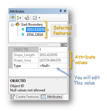
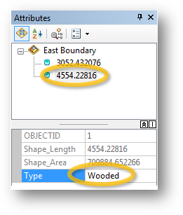
All selected polygons will be listed in the Attributes table editing environment. You should see two features. They are identified as their polygon perimeter (ArcGIS defaults to the first attribute value found in the attribute table).
Click on the top feature. This will highlight the left most polygon.
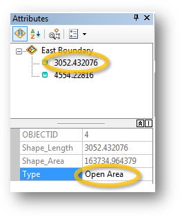
In the Type field, enter “Open area”.
Select the other polygon and enter Wooded for its Type.
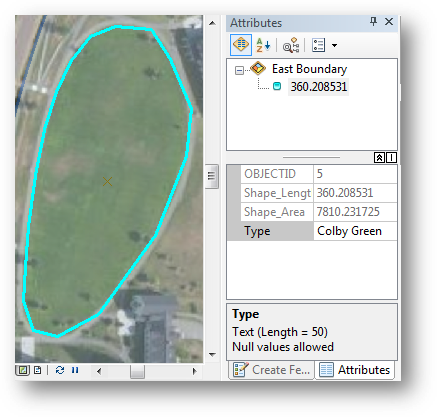
In the next step, you will digitize the Colby Green elliptical lawn.
In the previous step, you learned how to split a polygon into two sections. This required that the new polyline segment intersect the original polygon at two boundary points. But what if you need to create a new ‘Island’ polygon feature within the original polygon? The split tool will not work since you don’t have a boundary to snap to. You therefore will need to create a new polygon using the Polygon construction tool. But as you will soon find out, this approach has a serious pitfall that will need to be resolved.
At the bottom of the Attributes window, click on the Create Features tab.
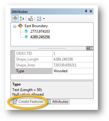
Note that you can toggle back and forth between the Attributes editor and the Creature Features window via the bottom tabs.
Clear all selected features by clicking the Clear Selected Features tool from the Tools toolbar.

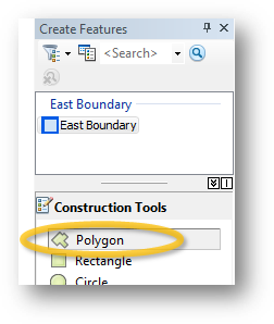
Make sure that East Boundary is selected in the Create Features window then select the Polygon tool from the Construction Tools list.
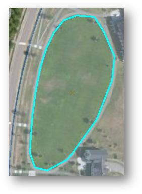
In the Data View window, digitize the Colby Green elliptical lawn. Follow the same techniques you used to digitize Johnson Pond in an earlier Step.
After you finish the Sketch, go back to the Attributes editor window.
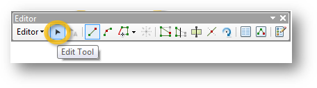
From the Editor toolbar select Edit Tool.
In the Data View window, select the polygon you just create.
After you select the polygon you will see the Selection
Chip tool ![]() appear. This tool appears when more
than one feature is selected. It allows you to fine tune your selection.
appear. This tool appears when more
than one feature is selected. It allows you to fine tune your selection.
Expand the Selection Chip.
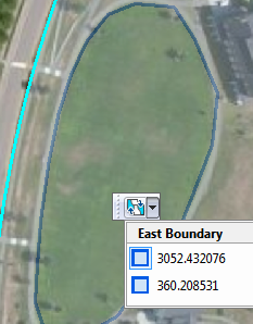
In our example, you have two polygons sharing the exact same space! In most cases, you do not want polygons within a same layer to overlap. By hovering over either one of the displayed features, the associated polygon will highlight in the Data View window.
Select the Colby Green polygon. This should be the second one on the list (note that the values displayed may differ from yours).
In the Editor toolbar, select Editor >> Clip.
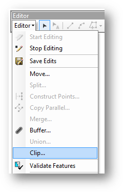
In the Clip tool set the Buffer Distance to 0 and select “Discard the area that intersects”.
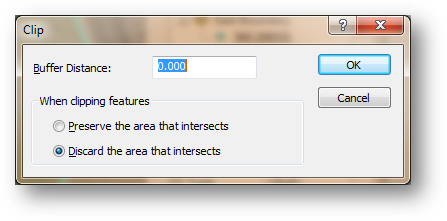
Click OK.
Go back to your map. Click in the Colby Green polygon with the Edit tool. Note that the Selection Chip tool does not appear. This indicates that you have no overlapping polygons.
Next, you will label the new polygon Colby Green.
Using the same procedures outlined in Step 7, name the new polygon Colby Green.
In the next step, you will add a polygon to the perimeter of the existing polygon
Zoom to the campus quad.
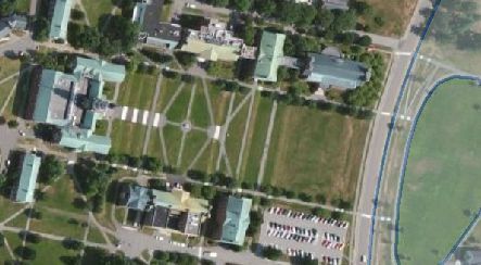
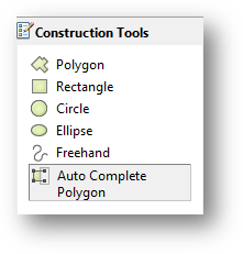
Next, you will digitize the quad and ensure that the new polygon shares the boundary with the existing East Boundary polygon. This will require using another specialized construction tool: Auto Complete Polygon.
In the Create Features window, select Auto Complete Polygon from the Construction Tools list.
Start the new polygon by snapping the first vertex to the existing East Boundary polygon then digitize the quad area. Make sure that the last vertex snaps to the East Boundary polygon.
Don’t forget to end the sketch by right-clicking and selecting Finish Sketch (or alternatively, press the F2 key).
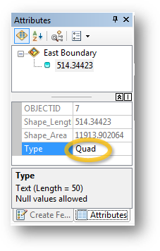
In the Attribute editor, name the new polygon “Quad”.
You are now done editing the East Boundary layer. You will save and stop your edit session.
From the Editor toolbar, select Save Edits.
From the Editor toolbar, select Stop Editing.
Next you will edit polyline features.
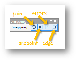
You have already been exposed to snapping when you split the polygon in an earlier step. By default, ArcMap is setup to snap to points, polyline endpoints, vertices and edges. When you are in an edit session, the snapping toolbar can be accessed from the Editor toolbar (Editor >> Snapping >> Snapping Toolbar).
Turn off the East Boundary layer and turn on the Roads layer.
Right-click on the Roads layer and select Edit Features >> Start Editing.
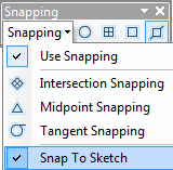
If the Snapping Toolbar is not already open go to the Editor toolbar, select Editor >> Snapping >> Snapping Toolbar.
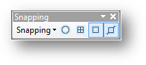
In the Snapping toolbar, turn off snapping for points and endpoints.
Using the Editor toolbar’s Edit Tool ![]() select Mayflower road.
select Mayflower road.
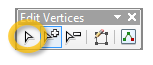
From the Editor toolbar, select the Edit Vertices tool.
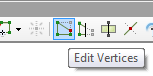
This brings up the Edit Vertices toolbar.
![]() .
.
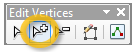
In the Edit Vertices toolbar, select Add Vertex.
In the Data View window, zoom in on the section of the road near the Colby Green lawn and the Diamond building.
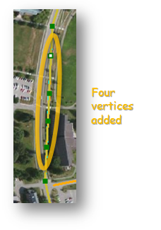
Note that a road segment does not accurately depict the true shape of the road represented in the aerial image. You will add four vertices to that segment
In the Data View window, add four vertices to the line segment. Their exact locations do not matter.
Next, you will move the vertices to the actual road outline.
Select the Modify Sketch Vertices tool from the Edit Vertices toolbar.
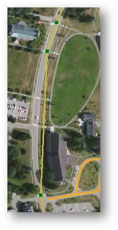
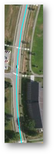
Next move the four new vertices in such a way that the polyline feature follows the road.
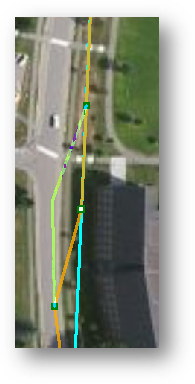
When complete, press the F2 key (this completes the edit sketch).
Your modified polyline feature should look like this:
Clear all selections (click on ![]() in the tool toolbar).
in the tool toolbar).
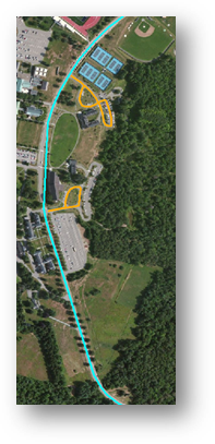
Select Alumni Lot from the Bookmarks pull-down menu.
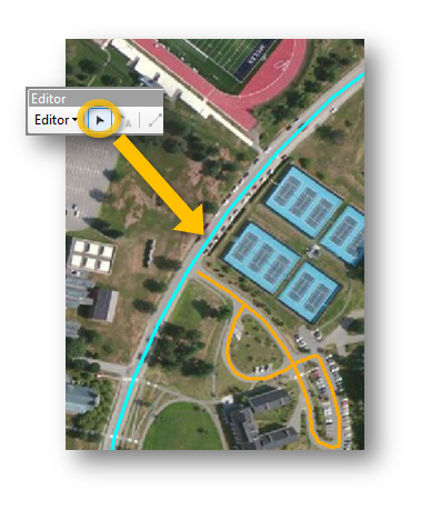
Notice that the Alumni Lot access road is not connected to the Mayflower Hill drive line segment. This needs to be corrected. One option is to move and snap the access road end-node to the Mayflower Hill road segment (while ensuring that the snap-to-edge is enabled). Another approach is to use one of ArcGIS’ advanced tools (Extend) to force the alumni lot access road to extend and snap to Mayflower Hill road.
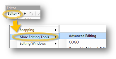
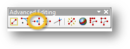
From the Editor toolbar, select Editor >> More Editing Tools >> Advanced Editing.
Select Mayflower Hill drive.
Note that when a line segment is selected, all of the Advanced Editing tools become active.
From the Advanced Editing toolbar, select the Extend tool.
Click anywhere along the tail-end of the Alumni lot access road. This action will extend that segment to the selected Mayflower Hill road line segment.
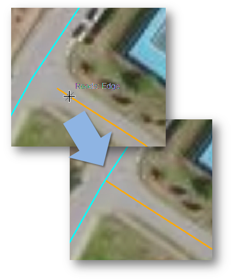
Next, you will add a road segment to the Alumni lot polyline feature. The new segment will need to connect to the existing road segment. This will require that the proper snap options are set.
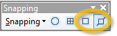
In the Snapping toolbar, ensure that the Edge Snapping and Vertex Snapping options are both active.
You will also want the new sketch to snap to itself.
In the Snapping toolbar, select Snapping >> Snap to Sketch.
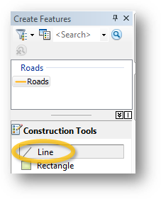
In the Create Features window, select the line construction tool (too see the tools the layer to be edited must active)
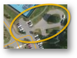
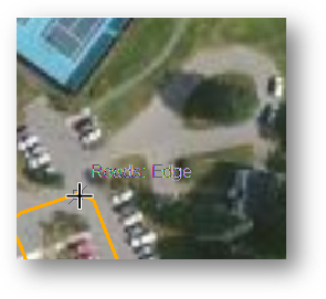
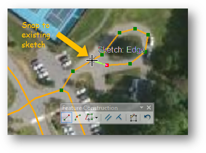
Hover the cursor anywhere over the existing line feature until it snaps (see graphic below).
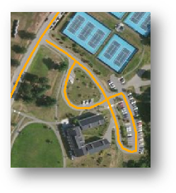
Create your first vertex on the existing line, and then continue digitizing the loop. Make sure that the other end of the line segment snaps to itself once it completes the loop.
Don’t forget to properly end the sketch (i.e. right-click >> Finish Sketch or press the F2 key).
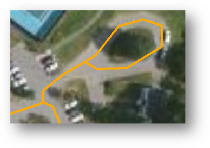
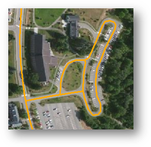
Next you will modify the Diamond/Lunder lot access road using the skills learned in Steps 12 and 13.
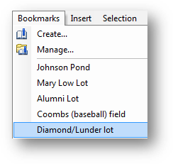
From the Bookmarks pull-down menu, select Diamond/Lunder lot.
You will add/modify the feature(s) such that the final layer looks like the following:
When done, save then stop your edit session and save ArcMap.
![]() Manuel Gimond, last modified on 8/26/2013
Manuel Gimond, last modified on 8/26/2013